SIMULATION WITH MASTER
A knowledge-based assistant for speeding up simulation projects.
Marco C. Bettoni and Willi Bernhard
Basle Institute of Technology, CIM Zentrum Muttenz
CH - 4132 Muttenz, Switzerland
m.bettoni@fhbb.ch and w.bernhard@fhbb.ch
Abstract
MASTER, the Muttenzer Assistant for Simulation Tasks with Expert Reasoning, is a hybrid simulation environment under development at the Basle Institute of Technology. MASTER should allow experienced, occasional or even unexperienced user to perform efficient simulation studies. In order to achieve this aim its architecture combines 'in parallel' a powerful general-purpose simulation language (SIMSCRIPT), knowledge-based modules developed with the KEE system and spread-sheet modules developed in LOTUS-123. The main function of the knowledge-based modules is to provide ease of use and intuitive understanding without compromising modeling flexibility and accuracy.We present here the background of the MASTER project - within the frame of the swiss federal CIM Upgrading Program - and the current state of implementation of three knowledge-based functions: model building, automatic code generation and the graphic, direct manipulation interface.
1. Introduction
The enterprise challenges of the 90's, like short product life cycles, built to order vs. built to stock, shorter technology life cycles and increased product complexity mean that the enterprise must perform frequent and incremental structural and organisational changes in order to survive on the marketplace [Van Dyke Parunak, 1992]. Rapid simulation studies can be an answer to the practical needs of enterprises confronted with such challenges.
2. Swiss federal CIM Upgrading Program
The CIM Zentrum Muttenz (CZM) belongs to a group of 7 swiss CIM Centers (technology upgrading centers) funded by the federal government in cooperation with the Cantons and with private business associations. These centers were initiated in 1991/92 in the frame of a federal CIM Upgrading Program ('CIM-Aktionsprogramm'), with the aim of strengthening the competitivity of the swiss economy, particularly that of small and medium sized enterprises (SME's). This competitivity depends at a large degree from the ability of the SME's in rapidly adopting the new technologies of computer integrated manufacturing (CIM).
3. CZM approach to simulation
In order to assist the diffusion of these technologies to SME's, the CIM Zentrum Muttenz focuses its activities on three main domains: technical training (education), counselling and technological development (R&D).
Simulation is becoming increasingly more important also for small and medium sized enterprises because the realisation of increasingly integrated and flexible systems means always a proportional increase in the risks of the enterprise investments. For this reason the simulation of enterprises has been defined by the CIM Upgrading Program as one of the nationwide technology upgrading topics. The CZM has acquired the responsibility of this topic and is performing here its main technological development effort. The aim of this effort is mainly to help the SME's in the solution of individual, specific simulation problems and then to transfer these individual project experiences to a larger SME public by means of counselling and training.
On this background, our concept of simulation focuses on the understanding of the dynamics of enterprise procedures and task flows; we conceive simulation as the activity of experimenting with the behavior of complex enterprise systems with the aim of increasing our understanding of their global behavior. SME's can use results from simulation experiments both to analyse and evaluate new or existing behaviors in the procedures and flows of their enterprises as well as to optimise (modify) them.
4. Services of the CZM in simulation
The range of simulation services offered by the CZM to small and medium sized enterprises falls into the general category of technology upgrading and can be divided into the following 6 groups:
- complete simulation projects: solution by a CZM simulation engineer of a specific simulation problem in cooperation with the experts of the firm;
- executable simulation models: delivery of a problem-specific, fixed model which can be used by the firm to run experiments by modifing a fixed set of parameters;
- counselling in simulation projects: technical advice and assistance to firms which want to make an own simulation study;
- orienting counselling: advice and assistance of about 1/2 to 1 day ;
- simulation pool: use by the SME's in their own projects of the advanced simulation equipment available at the CZM simulation lab;
- 'Erfa' group: organisation of technological information exchange (experiences) among SME's using simulation;
5. Requirements to simulation projects for SME's
Up to now SME's have not been very inclined in adopting simulation, mainly because accurate simulation projects have remained a difficult, time-consuming and expensive task [Stähly, 1992; Fox et.al., 1989, p.447]. Our way of helping SME's in the domain of simulation focuses on the so called "problem pull" as opposed to the widespread "technology push": the starting and reference point of our activities are the needs and practical problems of real firms not the availability of some new academic concepts and conceptual solutions. For this reason we have derived the following requirements to simulation projects from the needs and practical problems of SME's:
- Complex systems, practical problems. Also a small or a medium enterprise, if simulated in detail, becomes a complex system, especially when one - in order to have a model of practical relevance for the SME - needs to model not only the material flow, but also the concurrent information flow and value flow.
- Enterprise models. The evaluation of computer integrated technologies and facilities requires a global view of the enterprise: for this reason also the simulation must be able to overcome the limitations of individual departments and cope with the modelling of entire enterprises in one model.
- Rapid, low cost studies. The rapidity of changes on the marketplace requires from the SME's a high degree of flexibility. As a consequence, any simulation project can be of interest for an SME if and only if it can be executed rapidly and with low costs.
- Support cooperation with SME partners. A successful simulation project requires the involvement of the SME in contributing new ideas on the basis of its experience and practical knowledge of the business being analysed. In order to encourage this involvement the simulation technology adopted must support the cooperation of all partners of a project.
- Promoting the user's potentiality. Performing a simulation study should be an occasion human growth rather than an act of resignation to technical constraints [Volpert, 1991].
- Effectiveness (ease) of use. The diffusion of simulation know-how to participants in courses of technical training demands for the possibility of having unexperienced or occasional simulation user performing a simulation study. The need to make simulation easier comes also from the experienced simulation engineer, when he wants to fulfil in its projects all the requirements described above.
6. Services, requirements and the MASTER system
Provided that our objective is both to offer the above simulation services and at the same time to satisfy the above requirements, which would be the appropriate tool? In the attempt of answering this question, a simulation expert of the CZM evaluated a great number of simulation tools [Bernhard, 1991] and concluded that no one was appropriate to our objective. What we found out was that current tools (special-purpose packages and general-purpose languages) either 'compromise flexibility as a means of achieving ease of use' [Pegden, 1991, p.418] or compromise ease of use in order to provide modeling flexibility. Similarly to Pegden we came to the conclusion, that the appropriate tool should be one which 'does not require the user to select between ease of use ... and flexibility' [Pegden, 1991, p.418]; because of the lack of such a tool on the market we decided to develop MASTER. The position of MASTER relativly to the existing simulation tools can be graphically represented in a two-dimensional diagram of the 'modelling difficulty' and the 'modelling flexibility and accuracy': the place occupied by MASTER is in the upper left area, that of low difficulty and high flexibility.
7. The general design concept of MASTER
How to achieve in one tool both a high modelling flexibility and also a low modelling difficulty? Our approach was to combine in a hybrid simulation environment a powerful general-purpose language (SIMSCRIPT) with self-made modules which reduce as much as possible the modelling difficulty of the language and at the same time realize the other requirements presented above. This approach led to a design concept consisting of: I) a modelling technique; II) a general architecture. Because both these features have already been described elsewhere [Bernhard, 1992] we shall limit our presentation here to a brief summary.
The modelling technique of MASTER consists of a 3-level approach. At the first level, called 'Process Network', the user can describe its system by using a 'language' made of 7 elements: self-running processes, driven processes, queues, resources, timeless events, immediate flows and delayed flows. At the second level, called 'Process Specification', the user can describe in detail what happens in the processes and queues of the first level. This allows the user to define any control logic and any conditions or strategies of the modelled enterprise. At the third level, called 'Model Dictionary', the system collects all meanings of variables, attributes, parameters and other data entered by the user during the definition of the model in the first two levels.
The general architecture of MASTER consists of four packages embedded in a UNIX environment which communicate via ASCII files and cooperate to provide or allow eight main functions:
1. The KEE package is used to implement and run four knowledge-based functions: model building, automatic code generation, optimisation and a graphic, direct manipulation interface for accessing the other functions.
2. The SIMSCRIPT package provides the functions of running and debugging simulation models;
3. The SIMGRAPHICS package provides the function of concurrent and post-animation and is used to implement and run project specific animation interfaces;
4. The LOTUS-123 package is used to implement and run the functions of accounting postprocessing: output data analysis, presentation in business graphics and a specific postprocessing interface.
8. Graphic, direct manipulation interface
At present we are working on a 'research prototype' [Waterman, 1986, p.140] of the module of MASTER called COSIMO (COnstructs SImulation MOdels) which is intended as a playground for exploring a variety of approaches. This module includes the model building, automatic code generation and the user interface to these two functions.
The user interface is expected to: A) ensure effective use of the system's functions to any kind of users: experienced simulation engineers, occasional users and unexperienced persons who are learning simulation; B) promote the user's potentiality; C) support cooperation among all persons involved in a simulation project (users and non-users). This requires that the interface should: 1) ensure correct interactions under all conditions; 2) allow rapid sessions at any level of user's experience; 3) allow complete learning with minimal training; 3) contribute to a deeper understanding of the systems behavior and possibilities of its functions; 4) promote cooperation between the user and the 'assistant' system; 5) be understandable to any person who could contribute in the simulation study. 6) support the user in focusing its attention on its simulation task rather than on computer handling; 7) minimise the gap between the user's mental model of a simulation task and its realisation in the system.
Some of the principal guidelines available in current user-interface technology for realising these requirements are: 1) support a user-driven interaction control (instead of a system-driven); 2) avoid soliciting user input by interrogation; 3) let the user free to select different contexts; 4) guide and check user decisions by supporting interactions sensitive to context and to work in progress; 5) support user orientation (avoid that the user gets lost); 6) conform to the user's expectations and mental models as to how ideas are organised in the domain of simulation technology; 7) set on the user's visual abilities (instead of verbal abilities); 8) make the interface intuitive; 9) make easy the mechanics of interaction (minimise the memorisation of commands and the entering by typing).
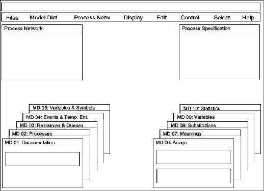
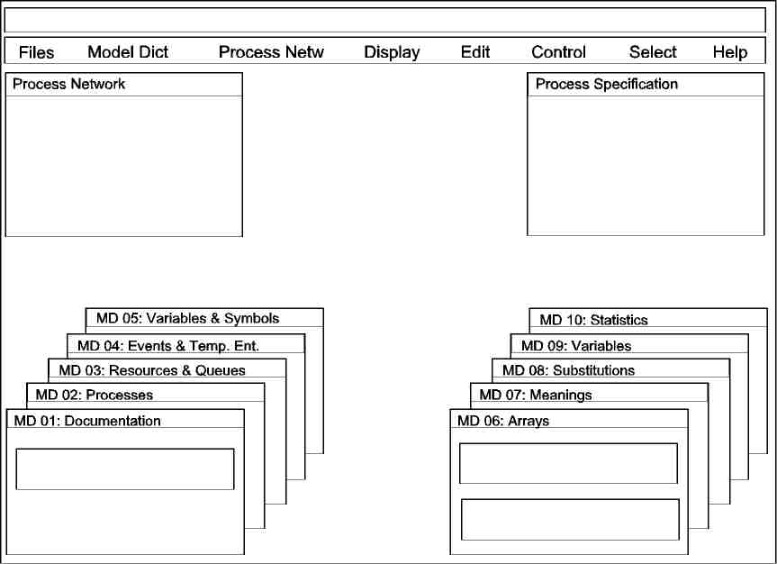
Figure 1: Standard main screen of MASTER
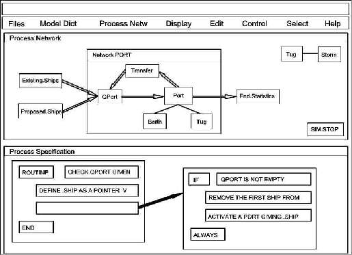
Figure 2: The 'Port Operation' model [Pritsker, 1986] in MASTER
MASTER's knowledge-based user interface is being developed with KEE and Lisp following these guidelines. Figure 1 shows the layout of the standard main screen. The upper rectangle is a prompt window for system messages. Below it is placed the main menu bar (mousing on an item opens a menu of additional items). The rest of the screen area is occupied by three groups of windows: a) windows for interacting with the process network (upper left corner); b) windows for interacting with the process specification (upper right corner); c) windows for interacting with the model dictionary (lower left and right corner);
In the standard main screen all windows have a reduced size and a fixed place. But the user can move, blow up, shrink and reshape them as she likes and needs. Figure 2 shows for example a modification of the standard screen by automatically blowing up first the 'Process Network' window and then the 'Process Specification' window: the two windows have been automatically expanded and occupy now each a half of the screen area below the menu bar.
9. Model building: the Process Network
According to MASTER's modelling technique the user begins constructing a new simulation model by 'translating' his mental model of the system into a network. The nodes of this network can be either processes (self-running or driven), queues, resources or events (see 7.); the connections between these nodes can be flows among processes and queues or bindings of resources to processes.
Figure 2 shows a process network based on the famous 'Port Operation' problem described by Pritsker and Schriber (Pritsker, 1986, p.195). When the user types the name of a node-element in the appropriate MD window (Fig.1) then the system invites her to choose a position in the 'Process Network' window and places there the appropriate picture (a colored rectangle). When the user wants to connect two nodes, the system asks her to mouse on them and adds the appropriate connection.
All these operations are supported by an object-oriented knowledge base ('KB-user') which changes its frame units (objects) as the modelling work progresses. For instance, when a node is added, the 'KB-user': a) creates a new model unit in the proper node hierarchy; b) creates a picture unit associated to the model unit; c) exposes the associated icon on screen. When a connection is added or removed, the 'KB-user': a) updates the appropriate slots (as upstream and downstream relations, etc.) in the frame units; b) updates the network window adding or removing a connecting line. The system supports also the full range of graphic functions like reshaping, moving, zooming.
The strict separation of model units (which store simulation model data) and picture units (which store graphic data) is used also to implement the well-known principle of 'hierarchical decomposition': the user can collect a group of pictures to a sub-network (Fig. 2, Network PORT) and then shut them down to a single picture, or he can begin by drawing a sub-network picture and subsequently refine it by defining the internal components. Both grouping and refining are performed in the same 'Process Network' window and can be continued to form a great number of hierarchical levels (in principle with no limits). The hierarchy concerns only the picture units and never the model units: this is why our solution can help the user in mastering model complexity but at the same time avoids implementation complexity.
10. Automatic code generation
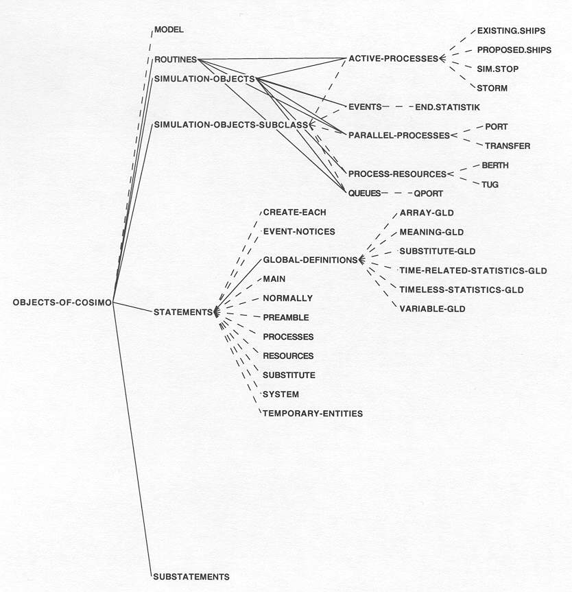
When the process network is completed, the user can load in in the model dictionary a file of appropriate default values for the declaration of statistics, variables, substitutions, meanings, arrays, etc.. These values are then visible in the input fields of the MD windows (Fig.1) and can be modified to fit the current project. When this is done the simulation model is complete enough to start the automatic code generation. During this process no user's action is necessary. The system transfers the relevant process network units (see 9.) from the 'KB-user' to the knowledge base which contains the code generation knowledge ('KB-code-objects'). Figure 3 shows a KEE graph of a part of the 'KB-code-objects' after the transfer operation. The model units (PORT, BERTH, TUG, etc.) exist now also in this KB and each of them will store the SIMSCRIPT statements which constitute their contribution to the complete code of the simulation model.
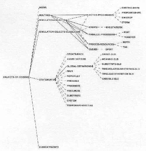
Figure 3: knowledge base of the code generation objects
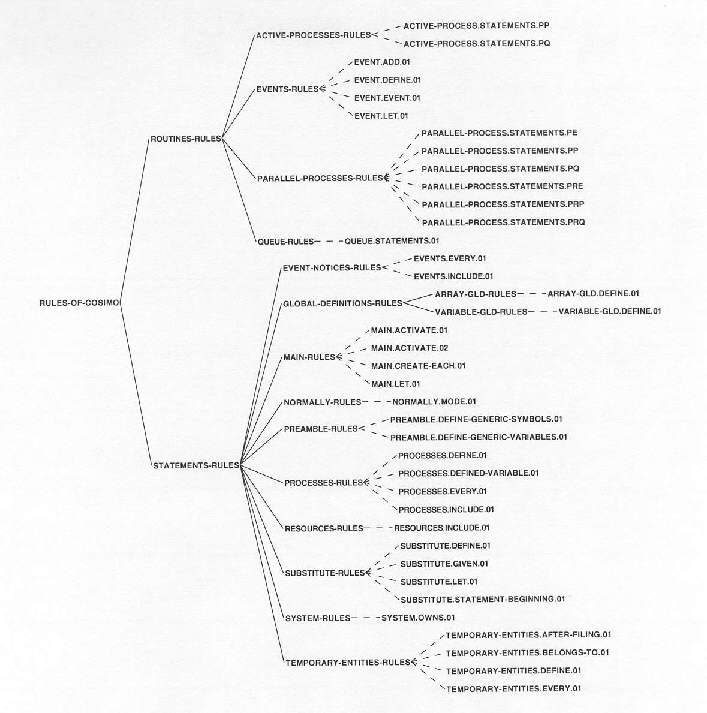
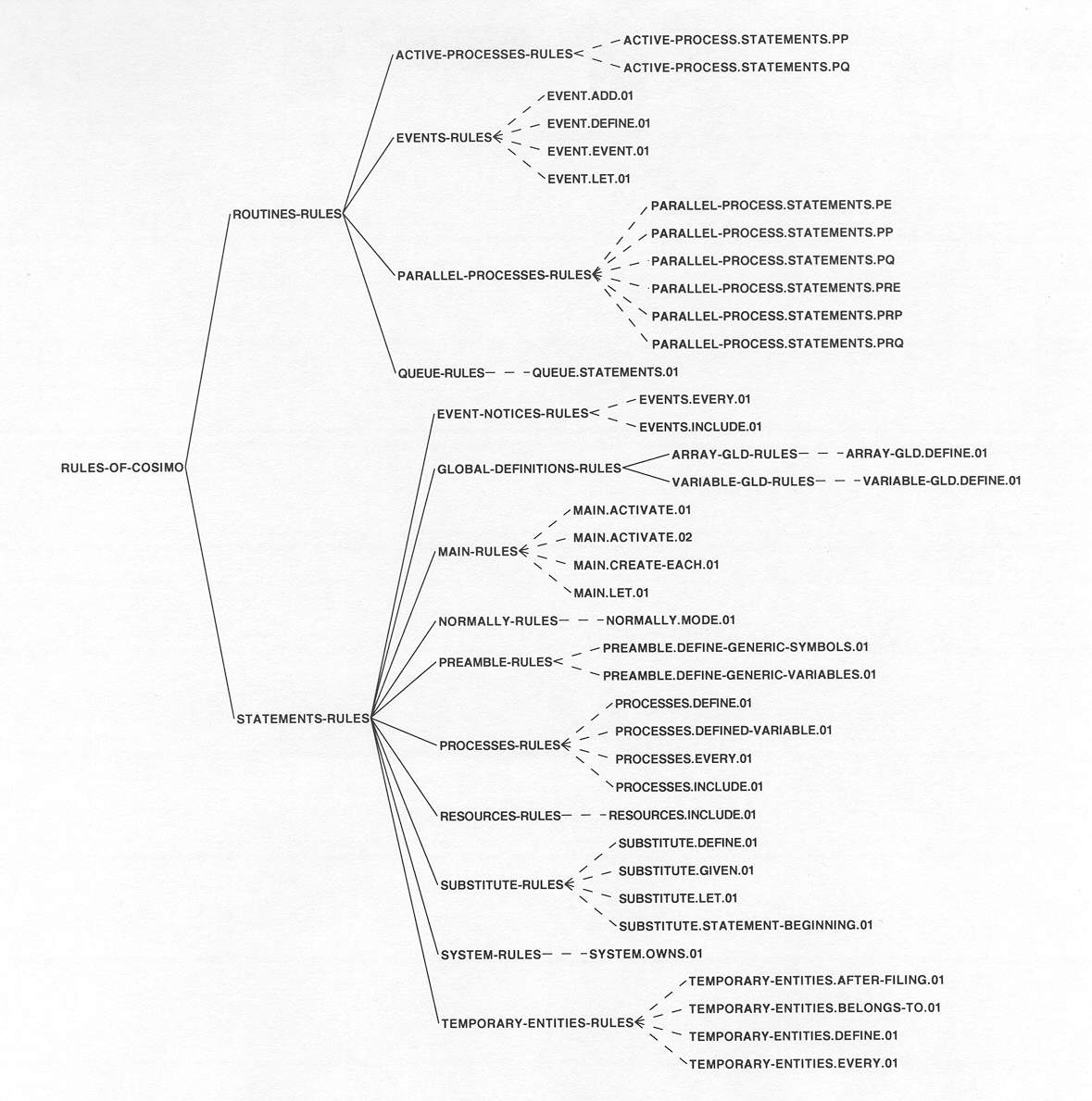
Figure 4: Knowledge base of the code generation rules
When the transfer operation is completed, the actual code generation can start. This process consists in a rule-based inference performed by forward chaining the rules of the knowledge base 'KB-code-rules' which represent the knowledge for controlling the code generation process. Figure 4 shows a KEE graph of this KB: an important feature of its design is that to each unit in the KB of code-objects corresponds a rule class in the KB of code-rules.
11. Model building: the Process Specification
After the automatic code generation all the three segments of the SIMSCRIPT program (Preamble, Main and Routines) are available, but they need further specification. Particularly the process and queue routines must be extended in order to obtain a complete, detailed description of the logic which controls the sequences of actions.
The user continues the construction of her simulation model (second level of MASTER's modelling technique) by 'translating' his mental model of the control logic and of all the conditions and strategies of the system into verbal descriptions. For instance, when the user wants to display and/or modify the statements of a routine, she mouses in the process network the target node and the system displays in the 'Process Specification' window a graphically structured representation of the routine statements currently stored in that node. Figure 2 shows the statements of the routine which specifies the queue 'QPort'. When the user has moused the node 'QPort', the system first fetches the routine statement strings stored in the QPort frame unit (Fig.3), then it activates a knowledge-based parser which returns a syntactically structured routine and finally it presents the parsed text in the boxes of a code card (see in Fig.2 the left rectangle in the process specification window). The boxes of this code card contain either a SIMSCRIPT keyword or a full statement, which can be further parsed. In Fig. 2 the user has activated the parsing of the statement containd in the third row of the code card: the system has first produced a second code card with the parsed text "if ... always" stored in its boxes and then connected this card with the box which contained the statement. The system supports also editing, adding, copying etc. of statement boxes, provides the full range of graphic functions like reshaping, moving, zooming and assists the user with knowledge-based features in the structured construction of new code cards.
12. Project Management
The development effort for the research prototype presented in this paper amounts today (Jan. 1993) at about 1000 hours divided in about 750 hours for pure development and about 250 hours used only for the administration of the HW and SW platform (Sun Sparcstation 2 with Sun OS 4.1.1, Open Windows 2.0, Lucid Lisp 4.0, GNU Emacs 18 and KEE 4.0).
The automatic code generation functions are planned to be improved and extended until the end of 1993 whereas work on the model building and the user interface functions will continue until the end of 1994.
References
Bernhard, W., Simulationstools - Stand der Technik. CIM Zentrum Muttenz, 1991.
Bernhard, W., Simulation of Enterprises. In: Krug, W., Lehmann, A., Simulation and AI in Computer-Aided Techniques, Proc. 1992 European Simulation Symposium, Dresden, pp. 566-571.
Fox, M.S. et.al., Knowledge-Based Simulation. In: Widman, Loparo, Nielsen, Artificial Intelligence, Simulation and Modeling. New York: John Wiley, 1989, pp.447-486.
Pegden, C.D., Manufacturing Simulation in the 90's. In: Mosekilde, E. (ed.), Modeling and Simulation 1991. Proc. European Simulation Multiconference, Copenhagen, pp.417-421.
Pritsker, A., An introduction to Simulation and SLAM-II. New York: Halsted Press, 1986.
Stähly, P., Simulation am IfU: Präsentation für CIM Zentrum Muttenz, Nov. 11, 1992, Hochschule St.Gallen.
Volpert, W., Die Spielräume der Menschen erhalten und ihre Fähigkeiten fördern. Gedanken zu einer sanften KI-Forschung., Paper presented at the GDI, Rüschlikon (Switzerland), June 28, 1991.
Waterman, D. A., A Guide to Expert Systems. Reading: Addison-Wesley, 1986.
![Figure 2: The 'Port Operation' model [Pritsker, 1986] in MASTER](port_screen.jpg)